Loading
-
67.
-
68.
-
69.
-
70.
-
71.
-
72.
Statement for Linked Answer Questions:
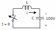
The L-C circuit shown in the figure has an inductance L=1mH and a
capacitance C = 10μF .
[1] The initial current through the inductor is zero, while the initial capacitor voltage is 100 V. The switch is closed at t = 0. The current i through the circuit is: [2 marks]
(A) 5cos (5 ×10³ t) A
(B) 5sin(104 t) A
(C) 10cos (5 ×10³ t) A
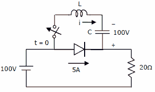
(D) 10sin(104 t) A[2] The L-C circuit of previous question is used to commutate a thyristor, which is initially carrying a current of 5A as shown in the figure below. The values and initial conditions of L and C are the same as in previous question. The switch is closed at t = 0. If the forward drop is negligible, the time taken for the device to turn off is 
[2 marks]
(A) 52μs
(B) 156μs
(C) 312μs
(D) 26μsasked in Electrical Engineering, 2010
View Comments [0 Reply]
