-
181.
Statement for Linked Answer Questions :
A general filter circuit is shown in the figure: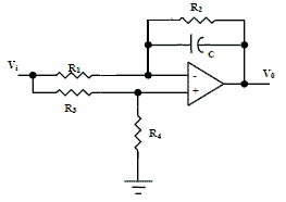
[1] If R1 = R2 = RA and R3 = R4 = RB, the circuit acts as a [2 marks]
(A) all pass filter
(B) band pass filter
(C) high pass filter
(D) low pass filter[2] The output of the filter in above question is given to the circuit shown in figure 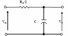
The gain vs frequency characteristic of output (Vo) will be [2 marks]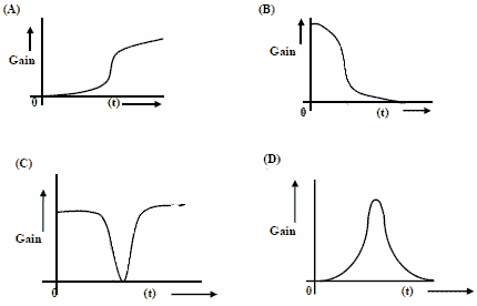
asked in Electrical Engineering, 2008
View Comments [0 Reply]
-
182.
Statement for Linked Answer Questions :
The state space equation of a system is described by x = Ax + Bu, y = Cx
where x is state vector, u is input, y is output and
[1] The transfer function G(s) of this system will be [2 marks]
(A) s/(s+2)
(B) s/(s-2)
(C) (s+1)/[s(s-2)]
(D) 1/[s(s+2)]
[2] A unity feedback is provided to the above system G(s) to make it a closed loop system as shown in figure. 
For a unit step input r(t), the steady state error in the output will be
[2 marks]
(A) 0
(B) 1
(C) 2
(D) ∞asked in Electrical Engineering, 2008
View Comments [0 Reply]
-
183.
Statement for Linked Answer Questions :
The current i(t) sketched in the figure flows through an initially uncharged 0.3 nF capacitor.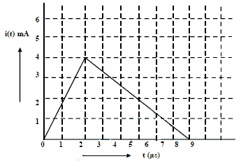
[1] The charge stored in the capacitor at t=5 μs, will be [2 marks]
(A) 8nC
(B) 10nC
(C) 13nC
(D) 16nC[2] The capacitor charged upto 5 μs, as per the current profile given in the figure, is connected across an inductor of 0.6 mH. Then the value of voltage across the capacitor after 1μs will approximately be [2 marks]
(A) 18.8 V
(B) 23.5 V
(C) -23.5 V
(D) -30.6 Vasked in Electrical Engineering, 2008
View Comments [0 Reply]
-
184.
A 3-phase, 440 V, 50Hz, 4-pole, slip ring induction motor is fed from the rotor side through an auto-transformer and the stator is connected to a variable resistance as shown in the figure.
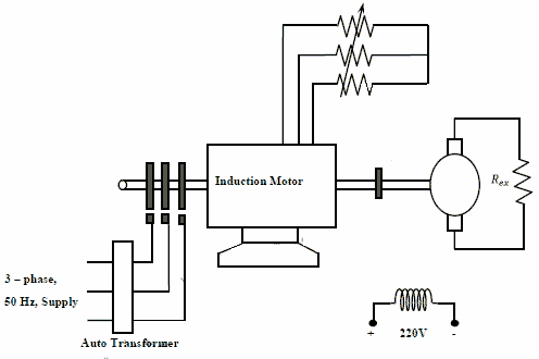
The motor is coupled to a 220 V, separately excited, dc generator feeding power to fixed resistance of 10 Ω. Two-wattmeter method is used to measure the input power to induction motor. The variable resistance is adjusted such that the motor runs at 1410 rpm and the following readings were recorded W1 = 1800 W, W2 = - 200 W.
[1] The speed of rotation of stator magnetic field with respect to rotor structure will be [2 marks]
(A) 90 rpm in the direction of rotation,
(B) 90 rpm in the opposite direction of rotation.
(C) 1500 rpm in the direction of rotation
(D) 1500 rpm in the opposite direction of rotation[2] Neglecting all losses of both the machines, the dc generator power output and the current through resistance (Rex) will respectively be
[2 marks]
(A) 96 W, 3.10 A
(B) 120 W, 3.46 A
(C) 1504 W, 12.26 A
(D) 1880 W, 13.71 Aasked in Electrical Engineering, 2008
View Comments [0 Reply]
-
185.
Consider a power system shown below

Given that: Vs1 = Vs2=1.0 + j0.0 pu;
The positive sequence impedance are Zs1= Zs2= 0.001 + j0.01 pu and ZL = 0.006 + j0.06 pu
3-phase Base MVA = 100
Voltage base = 400 kV(Line to Line)
Nominal system frequency = 50 Hz
The reference Voltage for phase ‘a’ is defined as v(t)=Vm cos(ωt).
A symmetrical three phase fault occurs at centre of the line, i.e. point 'F at time t0. The positive sequence impedance from source S1to point ‘F’ equals 0.004 + j0.04 pu. The waveform corresponding to phase 'a' fault current from bus X reveals that decaying dc offset current is negative and in magnitude at its maximum initial value. Assume that the negative sequence impedances are equal to positive sequence impedances, and the zero sequence impedances are three times positive sequence impedances.
[1] The instant (t0) of the fault will be [2 marks]
(A) 4.682 ms
(B) 9.667 ms
(C) 14.667 ms
(D) 19.667 ms[2] The rms value of the ac component of fault current (Ix) will be
[2 marks]
(A) 3.59 kA
(B) 5.07 kA
(C) 7.18 kA
(D) 10.15KA[3] Instead of the three phase fault, if a single line to ground fault occurs on phase 'a' at point ‘F’ with zero fault impedance, then the rms value of ac component of fault current(Ix)for phase 'a' will be [2 marks]
(A) 4.97pu
(B) 7.0pu
(C) 14.93pu
(D) 29.85puasked in Electrical Engineering, 2008
View Comments [0 Reply]
-
186.

