-
1.
Statement for Linked Answer Questions :
A synchronous motor is connected to an infinite bus 1.0pu voltage and draws 0.6 pu current at unity power factor. Its synchronous reactance is 1.0pu and resistance is negligible.[1] The excitation voltage (E) and load angle (δ) will respectively be
[2 marks]
(A) 0.8 pu and 36.86° lag
(B) 0.8pu and 36.86° lead
(C) 1.17 pu and 30.96° lead
(D) 1.17 pu and 30.96° lag[2] Keeping the excitation voltage same, the load on the motor is increased such that the motor current increase by 20%. The operating power will become
[2 marks]
(A) 0.995 leading
(B) 0.995 lagging
(C) 0.791 lagging
(D) 0.848 leadingasked in Electrical Engineering, 2008
View Comments [0 Reply]
-
2.
Statement for Linked Answer Questions :
A 240 V, dc shunt motor draws 15 A while supplying the rated load at a speed of 80rad/s. The armature resistance is 0.5 Ω and the field winding resistance is 80 Ω.[1] The net voltage across the armature resistance at the time of plugging will be
[2 marks]
(A) 6 V
(B) 234V
(C) 240 V
(D) 474 V[2] The external resistance to be added in the armature circuit to limit the armature current to 125% of its rated value is [2 marks]
(A) 31.1 Ω
(B) 31.9 Ω
(C) 15.1 Ω
(D) 15.9 Ωasked in Electrical Engineering, 2008
View Comments [0 Reply]
-
3.
Statement for Linked Answer Questions :
A general filter circuit is shown in the figure: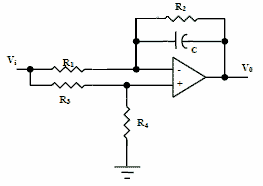
[1] If R1 = R2 = RA and R3 = R4 = RB, the circuit acts as a [2 marks]
(A) all pass filter
(B) band pass filter
(C) high pass filter
(D) low pass filter[2] The output of the filter in above question is given to the circuit shown in figure 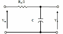
The gain vs frequency characteristic of output (Vo) will be [2 marks]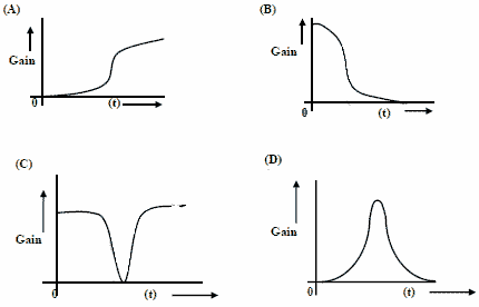
asked in Electrical Engineering, 2008
View Comments [0 Reply]
-
4.
Statement for Linked Answer Questions :
The state space equation of a system is described by x = Ax + Bu, y = Cx
where x is state vector, u is input, y is output and
[1] The transfer function G(s) of this system will be [2 marks]
(A) s/(s+2)
(B) s/(s-2)
(C) (s+1)/[s(s-2)]
(D) 1/[s(s+2)]
[2] A unity feedback is provided to the above system G(s) to make it a closed loop system as shown in figure. 
For a unit step input r(t), the steady state error in the output will be
[2 marks]
(A) 0
(B) 1
(C) 2
(D) ∞asked in Electrical Engineering, 2008
View Comments [0 Reply]
-
5.
Statement for Linked Answer Questions :
The current i(t) sketched in the figure flows through an initially uncharged 0.3 nF capacitor.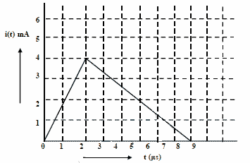
[1] The charge stored in the capacitor at t=5 μs, will be [2 marks]
(A) 8nC
(B) 10nC
(C) 13nC
(D) 16nC[2] The capacitor charged upto 5 μs, as per the current profile given in the figure, is connected across an inductor of 0.6 mH. Then the value of voltage across the capacitor after 1μs will approximately be [2 marks]
(A) 18.8 V
(B) 23.5 V
(C) -23.5 V
(D) -30.6 Vasked in Electrical Engineering, 2008
View Comments [0 Reply]
-
6.
A 3-phase, 440 V, 50Hz, 4-pole, slip ring induction motor is fed from the rotor side through an auto-transformer and the stator is connected to a variable resistance as shown in the figure.
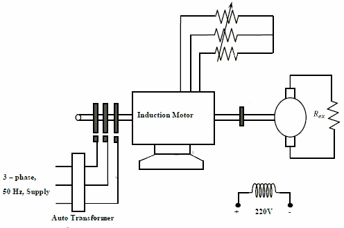
The motor is coupled to a 220 V, separately excited, dc generator feeding power to fixed resistance of 10 Ω. Two-wattmeter method is used to measure the input power to induction motor. The variable resistance is adjusted such that the motor runs at 1410 rpm and the following readings were recorded W1 = 1800 W, W2 = - 200 W.
[1] The speed of rotation of stator magnetic field with respect to rotor structure will be [2 marks]
(A) 90 rpm in the direction of rotation,
(B) 90 rpm in the opposite direction of rotation.
(C) 1500 rpm in the direction of rotation
(D) 1500 rpm in the opposite direction of rotation[2] Neglecting all losses of both the machines, the dc generator power output and the current through resistance (Rex) will respectively be
[2 marks]
(A) 96 W, 3.10 A
(B) 120 W, 3.46 A
(C) 1504 W, 12.26 A
(D) 1880 W, 13.71 Aasked in Electrical Engineering, 2008
View Comments [0 Reply]
