-
1.
Statement for Linked Answer Questions :
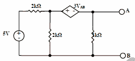
[1] For the circuit given above, the Thevenin’s resistance across the terminals A and B is [2 marks]
(A) 0.5kΩ
(B) 0.2kΩ
(C) 1kΩ
(D) 0.11kΩ[2] For the circuit given above, the Thevenin’s voltage across the terminals A and B is [2 marks]
(A) 1.25V
(B) 0.25V
(C) 1V
(D) 0.5Vasked in Electrical Engineering, 2009
View Comments [0 Reply]
-
2.
Statement for Linked Answer Questions :
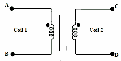
The figure above shows coils 1 and 2, with dot markings as shown, having 4000 and 6000 turns respectively. Both the coils have a rated current of 25A. Coil 1 is excited with single phase, 400V, 50Hz supply.
[1] The coils are to be connected to obtain a single phase, 400/1000V, auto- transformer to drive a load of 10kVA. Which of the options given should be exercised to realize the required auto-transformer? [2 marks]
(A) Connect A and D; Common B
(B) Connect B and D; Common C
(C) Connect A and C; Common B
(D) Connect A and C; Common D[2] In the autotransformer obtained in above Question, the current in each coil is
[2 marks]
(A) Coil-1 is 25 A and Coil-2 is 10 A
(B) Coil-1 is 10 A and Coil-2 is 25 A
(C) Coil-1 is 10 A and Coil-2 is 15 A
(D) Coil-1 is 15 A and Coil-2 is 10 Aasked in Electrical Engineering, 2009
View Comments [0 Reply]
-
3.
A system is described by the following state and output equations
dx1(t)/dt = -3x1(t) +x2(t) + 2u(t)
dx2(t)/dt = -2x2(t) + u(t)
y(t) = x1(t)
where u(t) is the input and y(t) is the output.
[1] The system transfer function is [2 marks]
(A) (s+2)/(s2+5s-6)
(A) (s+3)/(s2+5s+6)
(A) (2s+5)/(s2+5s+6)
(A) (2s-5)/(s2+5s-6)
[2] The state-transition matrix of the above system is [2 marks] 
asked in Electrical Engineering, 2009
View Comments [0 Reply]
-
4.
The circuit diagram shows a two winding, lossless transformer with no leakage flux, excited from a current source, i(t), whose waveform is also shown. The transformer has a magnetizing inductance of (400/π) mH.
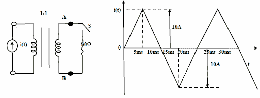
[1] The peak voltage across A and B, with S open is [2 marks]
(A) 400/πV
(B) 800V
(C) 4000/πV
(D) 800/πV[2] If the waveform of i(t) is changed to i(t)=10sin(100 πt) A, the peak voltage across A and B with S closed is [2 marks]
(A) 400V
(B) 240V
(C) 320V
(D) 160Vasked in Electrical Engineering, 2009
View Comments [0 Reply]
-
5.
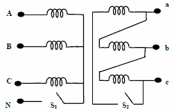
The star-delta transformer shown above is excited on the star side with a balanced, 4-wire, 3-phase, sinusoidal voltage supply of rated magnitude. The transformer is under no load condition.
[1] With both S1 and S2 open, the core flux waveform will be [2 marks]
(A) a sinusoid at fundamental frequency
(B) flat- topped with third harmonic
(C) peaky with third- harmonic
(D) none of these[2] With S2 closed and S1 open, the current waveform in the delta winding will be [2 marks]
(A) a sinusoid at fundamental frequency
(B) flat- topped with third harmonic
(C) only third harmonic
(D) none of theseasked in Electrical Engineering, 2009
View Comments [0 Reply]
-
6.

