Loading
-
697.
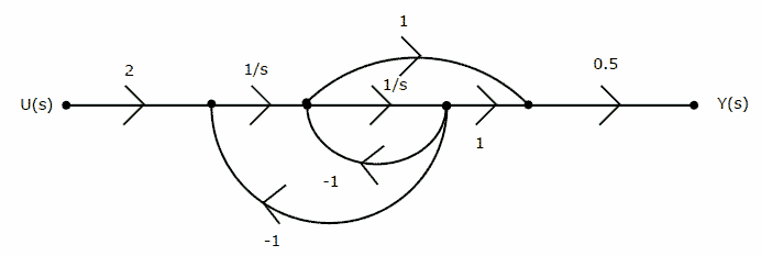
The signal flow graph of a system is shown below.

[1] The state variable representation of the system can be [2 marks] 
[2] The transfer function of the system is [2 marks]
(A) (s+1)/(s2+1)
(B) (s-1)/(s2+1)
(C) (s+1)/(s2+s+1)
(D) (s-1)/(s2+s+1)
asked in Electronics and Communication Engineering, 2010
View Comments [0 Reply]
-
698.
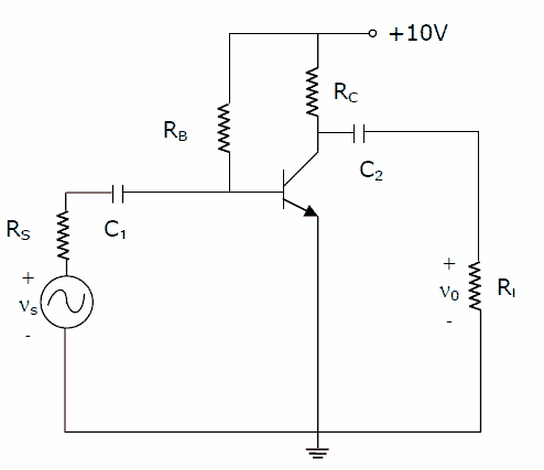
Consider the common emitter amplifier shown below with the following circuit
parameters:
b=100, gm=0.3861 A/V, r0=∞ , rp=259 W, RS=1kW, RB=93KW, RC=250 W, RL=1kW, C1=∞ and C2=4.7mF.
[1] The resistance seen by the source Vs is [2 marks]
(A) 258 Ω
(B) 1258 Ω
(C) 93 KΩ
(D) ∞[2] The lower cut-off frequency due to C2 is [2 marks]
(A) 33.9 Hz
(B) 27.1 Hz
(C) 13.6 Hz
(D) 16.9 Hzasked in Electronics and Communication Engineering, 2010
View Comments [0 Reply]
-
699.
-
700.
-
701.
-
702.


