Loading
-
193.
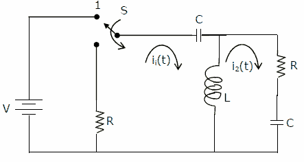
The circuit is given in figure. For both the questions, assume that the switch S is in position 1 for a long time and thrown to position 2 at t = 0.

[1] At t = 0+, the current i1 is [2 marks]
(a) -V/2R
(b) -V/R
(c) -V/4R
(d) zero
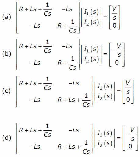
[2] I1(s) and I2(s) are the Laplace transforms of i1(t) and i2(t) respectively. The equations for the loop currents I1(s) and I2(s) for the circuit shown in figure, after the switch is brought from position 1 to position 2 at t = 0, are
[2 marks]
asked in Electronics and Communication Engineering, 2003
View Comments [0 Reply]
-
194.
-
195.
-
196.
-
197.
-
198.

